Altera Nios II FreeRTOS Demo
Running on a Cyclone III FPGA
[RTOS Ports]
This demo was developed on a DBC3C40 reference design from
EBV Elektronik - based on an Altera Cyclone III FPGA.
The FPGA and software can be configured and compiled using the free web edition of
Quartus II and the Nios II Embedded Design Suite.
Note that this port was originally written using a pre-version 9 version of the design tools. Calvin Ruben
has been good enough to keep the project up to date, and posted a version to the FreeRTOS Interactive pages
that is compatible with both version 9.1 and version 10 of the Altera tools. On behalf of the FreeRTOS community I would like to thank Calvin for his contribution.
IMPORTANT! Notes on using the Altera Nios II Demo
Please read all the following points before using this RTOS port.
- Source Code Organisation
- The Demo Application
- RTOS Configuration and Usage Details
See also the FAQ My application does not run, what could be wrong?
Source Code Organisation
The Nios II IDE project file is located in the FreeRTOS/Demo/NiosII_CycloneIII_DBC3C40_GCC directory. This is the
directory to select when importing the project into your IDE workspace.
The FreeRTOS zip file download contains the files for all the ports and demo application projects. It therefore contains many more
files than used by this demo. See the Source Code Organization section for a description
of the downloaded files and information on creating a new project.
The Demo Application
Creating the project directory structure
The Nios II IDE is a customised version of Eclipse.
The easiest way to use an Eclipse managed make build is to locate the required build files (C source files, header files and linker scripts)
under the directory that contains the Eclipse project file. The FreeRTOS download contains a batch file called CreateProjectDirectoryStructure.bat
that will copy all the required build files from their normal locations within the FreeRTOS directory structure to sub directories under
the Eclipse project directory. The batch file is located in the FreeRTOS/Demo/NiosII_CycloneIII_DBC3C40_GCC directory and must be executed prior to importing the project into
the Nios II IDE.
Execute CreateProjectDirectoryStructure.bat from either a command prompt or Windows explorer. It cannot be executed successfully from within
the Eclipse environment itself.
Note! CreateProjectDirectoryStructure.bat must be executed before the demo project is imported into the Nios II IDE, otherwise the
include paths stored within the project will be destroyed.
Importing the project into the Nios II IDE workspace
- Note! CreateProjectDirectoryStructure.bat must be executed before the
demo project is imported into the Nios II IDE. Instructions are provided above.
- Start the Nios II IDE. As it starts up you may be prompted for a workspace location. You can use your existing workspace or create a new one in a
convenient directory.
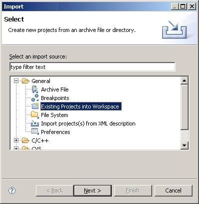
- Within the Nios II IDE, select 'Import...' from the 'File' menu.
- A dialog box will appear. Select 'Existing Projects Into Workspace', then click 'Next'.
- Browse to and select the FreeRTOS/Demo/NiosII_CycloneIII_DBC3C40_GCC directory. The directory contains two projects - one called RTOSDemo and the other
called RTOSDemo_syslib.
- Ensure both projects are selected and that the 'Copy projects into workspace' check box is not selected before completing the import process.

Importing the FreeRTOS projects into the Nios II IDE workspaceDemo Application Hardware Setup
The CD that accompanies the DBC3C40 reference design includes a selection of .sof files that implement various different Nios II configurations. The demo presented on this
page was developed using TFT.sof.
The demo uses the LEDs built onto the DBC3C40 itself. The functions that control the LEDs are implemented within
FreeRTOS/Demo/NiosII_CycloneIII_DBC3C40_GCC/RTOSDemo/ParTest/ParTest.c These functions may require modification if a hardware platform with a different IO
configuration is being used.
The demo includes the 'ComTest' tasks where one task transmits characters on a UART that are then received by another task. An error is latched if any characters
are received out of sequence or are simply missing. A loopback connector must be fitted to the UART for the mechanism to work - simply connect the UART Rx pin to
the UART Tx pin.
Building and executing the demo application
- Open main.c and search for a line that starts "#error". Delete the line (it provides instructions on setting up the directory
structure for those using the project without first reading these instructions).
- Connect the target hardware to the host computer using a programming and debug interface - an Altera USB Blaster is suitable for this purpose.
- To build the project, simply select 'Build All' from the 'Project' menu. The application should build with no errors
or warnings (assuming the #error statement has been removed and CreateProjectDirectoryStructure.bat has been executed). The initial
build will take some time as it generates the entire system library.
- A launch configuration needs to be created before a debug session can be started. This only needs to be done once, after
it has been created debug sessions can be started simply by clicking the 'Debug' speed button. To create a launch configuration,
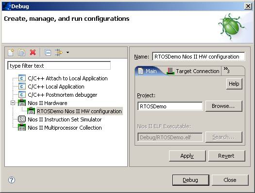
first select the 'RTOSDemo' project within the IDE Projects window, then select 'Debug...' from the 'Run' menu.
- In the dialog box that opens, double click where it says 'Nios II hardware' to create a new configuration. The configuration
parameters will be set automatically.
- Finally click 'Debug' to program the MCU and start a debug session.
The first download attempt will cause the Nios II IDE to automatically open the Quartus II programmer, from where a .sof file can be opened and
programmed into the FPGA. Once the .sof file has been downloaded the debug speed button can be
clicked to re-run the debug launch configuration. This is only necessary the first time after the FPGA has been powered up.

Setting up the launch configuration
Functionality
The demo application creates 43 tasks prior to starting the RTOS scheduler. These tasks consist
mainly of the standard demo application tasks (see the demo application
section for details of the individual tasks). Their only purpose is to test the RTOS kernel port and provide
a demonstration of how to use the various API functions.
The following tasks and tests are created in addition to the standard demo tasks:
- Check task
This only executes every five seconds. Its main function is to check that all the
standard demo tasks are still operational. The Check task will toggle LED 7 every 5 seconds provided all
the tasks in the system are executing without error. The toggle rate increasing to 500ms is indicative of
an error being reported in at least one task - the name of the offending task will be written to the
Nios II IDE terminal. This mechanism can be tested by removing the loop back connector from the UART and in
so doing deliberately introducing an error.
- Reg Test tasks
The reg test tasks fill the Nios II registers with known values before checking each register contains the value expected.
A register containing an unexpected value is indicative of an error in the context switch mechanism. Two reg test tasks
are created, with each using a different set of register values.
When executing correctly the demo application will behave as follows:
- LEDs 0, 1 and 2 are under the control of the standard 'flash' tasks. Each will toggle at a different but fixed frequency.
- LEDs 4 and 5 are under the control of the ComTest tasks - one will toggle each time a character is transmitted and the other each time a character is
correctly received.
- LED 7 is under the control of the Check task (as described above). It will toggle every 5 seconds.
RTOS port specific configuration
Configuration items specific to these demos are contained in FreeRTOS/Demo/NiosII_CycloneIII_DBC3C40_GCC/RTOSDemo/FreeRTOSConfig.h. The
constants defined in this file can be edited to suit your application. In particular configTICK_RATE_HZ which sets the frequency of the RTOS tick.
The supplied value of 1000Hz is useful for testing the RTOS kernel functionality but is faster than most applications require. Lowering this value will improve efficiency.
Each port #defines 'BaseType_t' to equal the most efficient data type for that processor. This port defines
BaseType_t to be of type long.
Note that vPortEndScheduler() has not been implemented.
Interrupt service routines
The interrupt entry point is contained within the RTOS kernel port layer itself (within FreeRTOS/Source/portable/GCC/Nios II/port_asm.S) and is written
to be compatible with the Altera HAL. This means interrupt service routines can be written in accordance with the Altera HAL documentation, and can be
registered using the standard HAL alt_irq_register() function.
Sometimes it is desirable for an interrupt service routine to interrupt one task, but return to another. This would be the case if the interrupt service
routine caused a task to unblock, and the unblocked task had a priority higher than the currently executing task. The macro portEND_SWITCHING_ISR() is provided
to allow an interrupt service routine to request a context switch - pass zero to portEND_SWITCHING_ISR() if a context switch is not required, or a non-zero value
if a context switch is required.
See FreeRTOS/Demo/NiosII_CycloneIII_DBC3C40_GCC/RTOSDemo/serial.c for an example interrupt service routine and an example use of portEND_SWITCHING_ISR().
Memory allocation
Source/Portable/MemMang/heap_2.c is included in the demo application project to provide the memory
allocation required by the RTOS kernel.
Please refer to the Memory Management section of the API documentation for
full information.
Copyright (C) Amazon Web Services, Inc. or its affiliates. All rights reserved.
|


